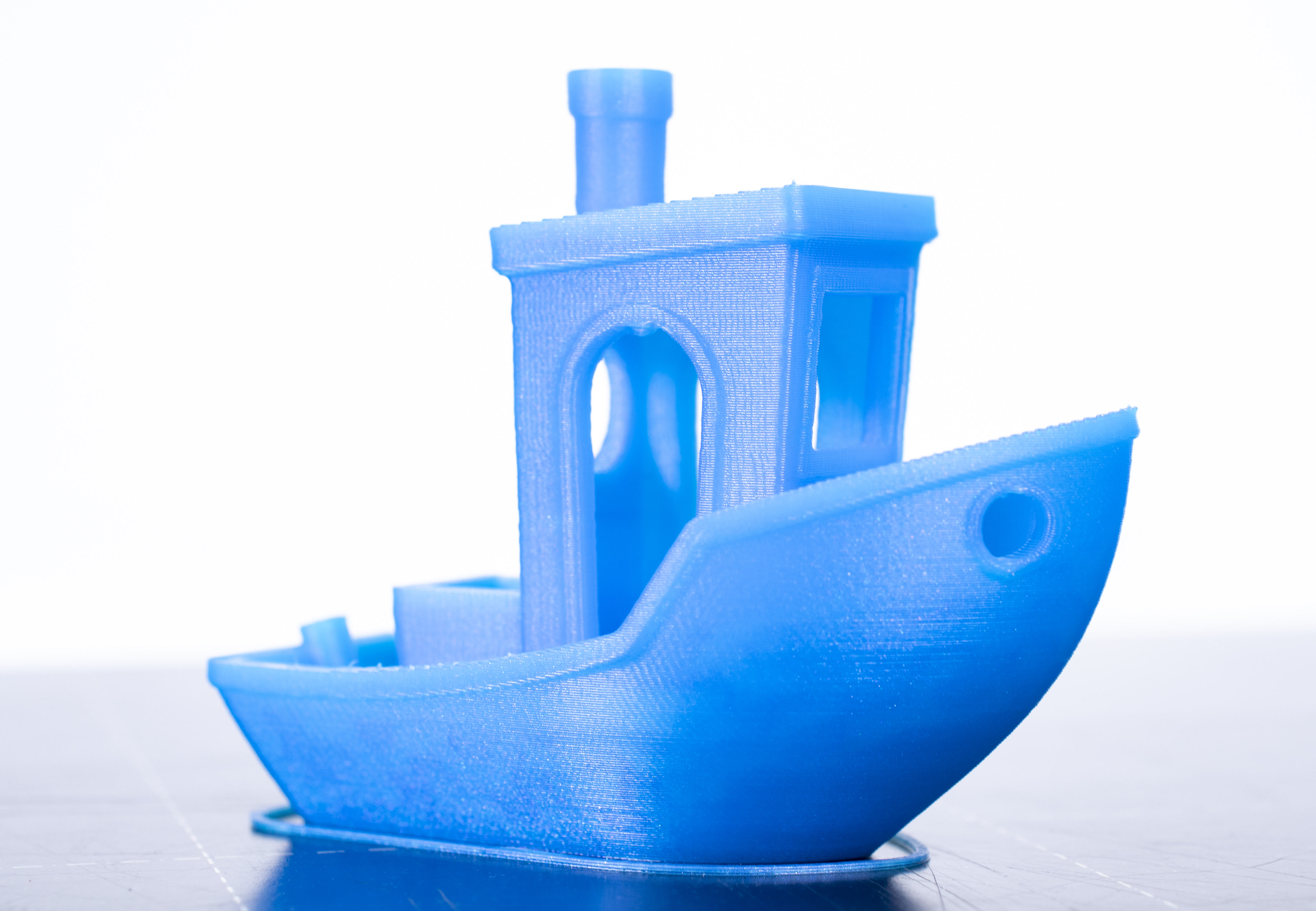
The 3DBenchy is a 3D model designed by CreativeTools specifically for testing and benchmarking 3D printers. And everyone wants to know, how to print a perfect Benchy. Ever since it’s release, one specific problem seems to be present, in varying degrees of severity, in all of its prints - the infamous Benchy hull line.

It’s visible on prints from all FFF printers on the market, cheap or expensive. It’s visible no matter the slicing software. It’s visible when printing from any material. It’s visible even in the Benchy release video from 2015. Again, in varying degrees of severity - with some combinations of printer, slicer, and material, it can be almost invisible. Other times, it’s clearly defined, leaving the user disappointed and confused. But once you see it, you’ll be able to find it on essentially all of its prints.
The good news is that we managed to mostly eliminate the Benchy hull line in our sample G-codes (not in 100% cases though, more on that later). You can download the G-code here.
The bad news is that the fix isn’t universal.And we’re not even sure if such universal fix is physically possible to exist.
New Benchy sample G-code printed on the MK3S
A hardware problem?
When you search for the problem online, you’ll often get an (incorrect) suggestion, that it might be a hardware problem. To give you an example, here are some of the suggestions we found online:
- loose belts
- bent Z-axis rods
- irregularity in your z-axis lead screw at that height
The culprit
We believe that the main culprit is the sudden transition from sparse infill into full top layers around the 8 mm height (may vary a bit depending on your layer height and number of top layers).
At this point, there is an abrupt difference in the time a layer takes to print.
And a few layers later, another sudden change happens. When the deck is finished it’s no longer an almost solid layer, but just a few perimeters again.
Here are the factors that influence the severity of the Benchy hull line
- Filament material thermal expansion coefficient
- Print cooling
- Print environment
- Other filament properties - dryness, composition
A seemingly similar, yet partly different problem is when printing boxes. They also tend to have a line at the height where the bottom solid layers transition into walls. This has more to do with thin walls, extrusion width, and the material has nowhere to go, but outside. Our slicer team knows about this problem and it's something that will likely improve in the future.
Why can’t the slicer automatically detect and correct for this?
It’s physics. Plastics, if extruded first from pellets into a filament, and then from filament into a very thin rectangular extrusion, will behave neither as a liquid nor as a solid. The stretching of the plastic will align the long molecular chains of the polymer, introducing internal stresses to the extrusion. This internal stress will pull the extrusion together if not cooled quickly enough. For example, on the MK2 the 3D Benchy has the line more pronounced on the side away from the cooling fan.
It depends on the environment too. Indeed, as many of you found out, in a cool basement the effects are more pronounced. The same G-code printed on the same printer with the same filament can have a Benchy hull line in one room and not in the other. It’s very difficult to automatically compensate for that.
And to compensate for the internal stresses and cooling effects of the filament. One of the reasons being the viscoelastic behavior of the molten plastics, and the dependence of the plastic behavior on its composition, temperature, hydrolysis of the polymer molecular chains. If the filament is not 100% dry (polyesters - PLA & PET are sensitive to hydrolysis, hydrolyzed filament contains shorter polymer chains, thus being less viscous), the effectivity of the cooling, reflections of the cooling air from the already printed objects, etc.
How did we modify the G-code to eliminate it?
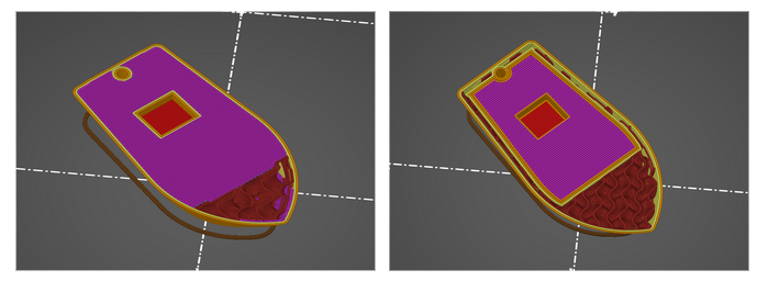
Something that helps, is to make a modifier mesh in the shape of the deck. When aligned at the problematic spot, it can be used to split the hull and the deck. They are then printed separately, plus the infill doesn’t fill the entire area all the way to the hull perimeters.
Then there’s the order of elements inside a layer. For some reason, we got better results when always printing the deck perimeters first, then infill of the deck and then the rest of the layer. We manually edited this order using a text editor.
We’re not sure if it ended up helping, but we also manually edited the G-code in order to slightly lower the flow of solid infill, except for the very top layer (of the deck).
Another thing is to print the perimeters as continuously as possible. Rather than printing perimeters, then infill and then transitioning to the next layer it’s better to print two (or more) layers of perimeters one right after another. The printer then can go back and print the infill, again two layers at a time.
We most likely haven’t discovered all factors and in precisely what ratios they influence the severity of the Benchy hull line. Still, we wanted to share our findings. If you make your own research and tests, let us know of your findings.
15 comments
enclosed units compensate a bit for this but doesnt negate the issue. adjust travel speeds and flow rate accordingly and it smooths out. also changing order of wall prints can help depending on the model's geometry. for example bambu studio defaults to inner/outer. forcing outer/inner will let the outer perimeter cool down better and keep its accuracy
This line will made me crasy during long long time.
I use SuperSliecr, is similar to PrsaSlicer. And i have a DIY 3D printer.
Recently i have find a solution to avoid this line by enable or disable differents parameters :
- Disable Overlaping external perimeters
- Disable Thin Walls
- Activate External perimeter first
-> To apply on Outer and Inter side
For me is a nice solution. I think the main parameter wich avoid this ligne is the Overlaping external perimeters an Thin Walls. In some layer you need a verry small wall to finish the outer. and other, no. So n some case there is more material on wall and a tension of the plasic.
This is my analyse, but maybe it depend of machin, extruedr, material, ...