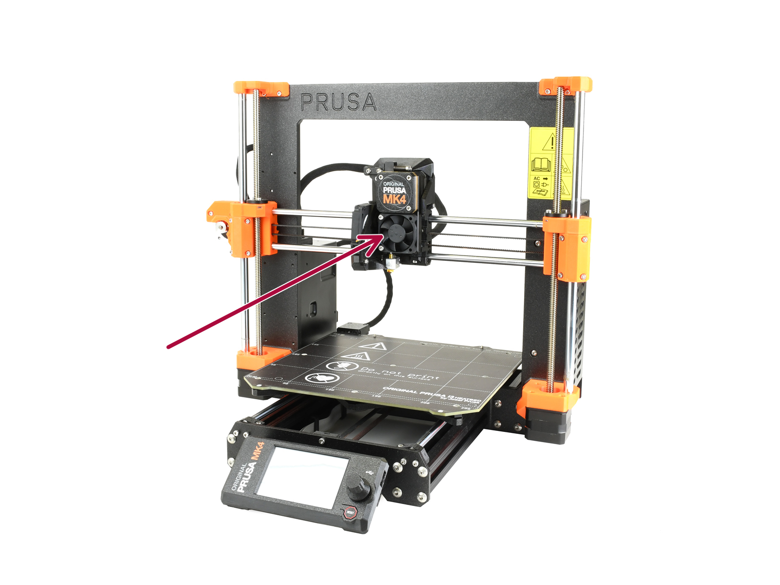
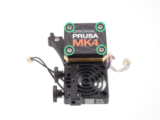
EN
  • Čeština
  • Italiano
  • Deutsch
  • Polski
  • Français
Login

How to replace a hotend heatsink (MK4 / MK3.9)

Menu

How to replace a hotend heatsink (MK4 / MK3.9)

How to replace a hotend heatsink (MK4 / MK3.9)
Relevant for:
Last updated 10 days ago
How to replace a hotend heatsink (MK4 / MK3.9)
 Difficulty
Difficult
 Steps
41
 Available languages
CSPLDEITFR
Introduction
Introduction
This guide will take you through the Hotend Heatsink replacement on your Original Prusa MK4 or MK3.9.
All necessary parts are available in our eshop prusa3d.com.
Note that you have to be logged in to have access to the spare parts section.
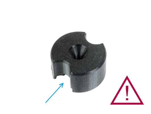
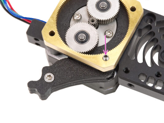
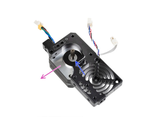
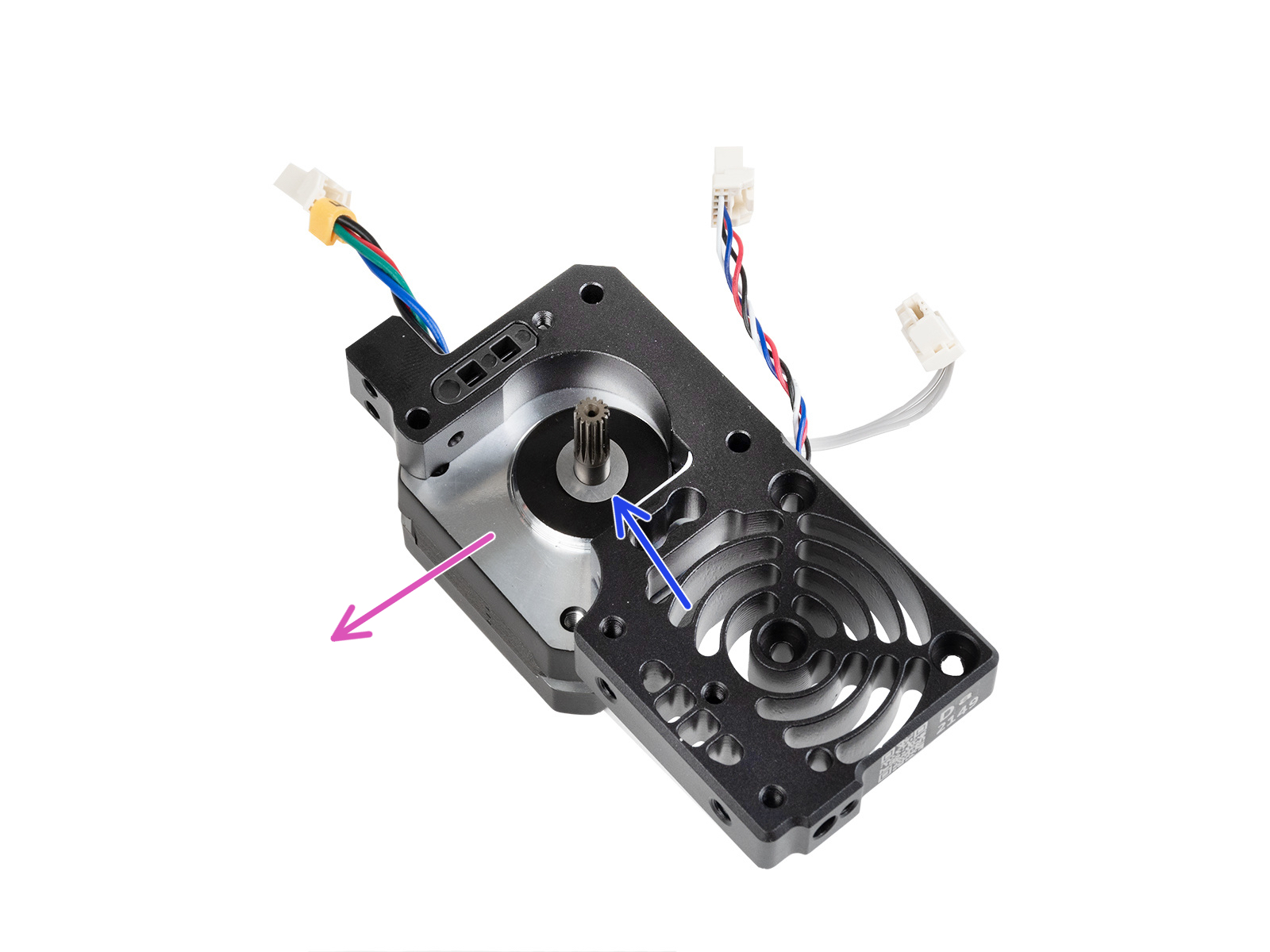
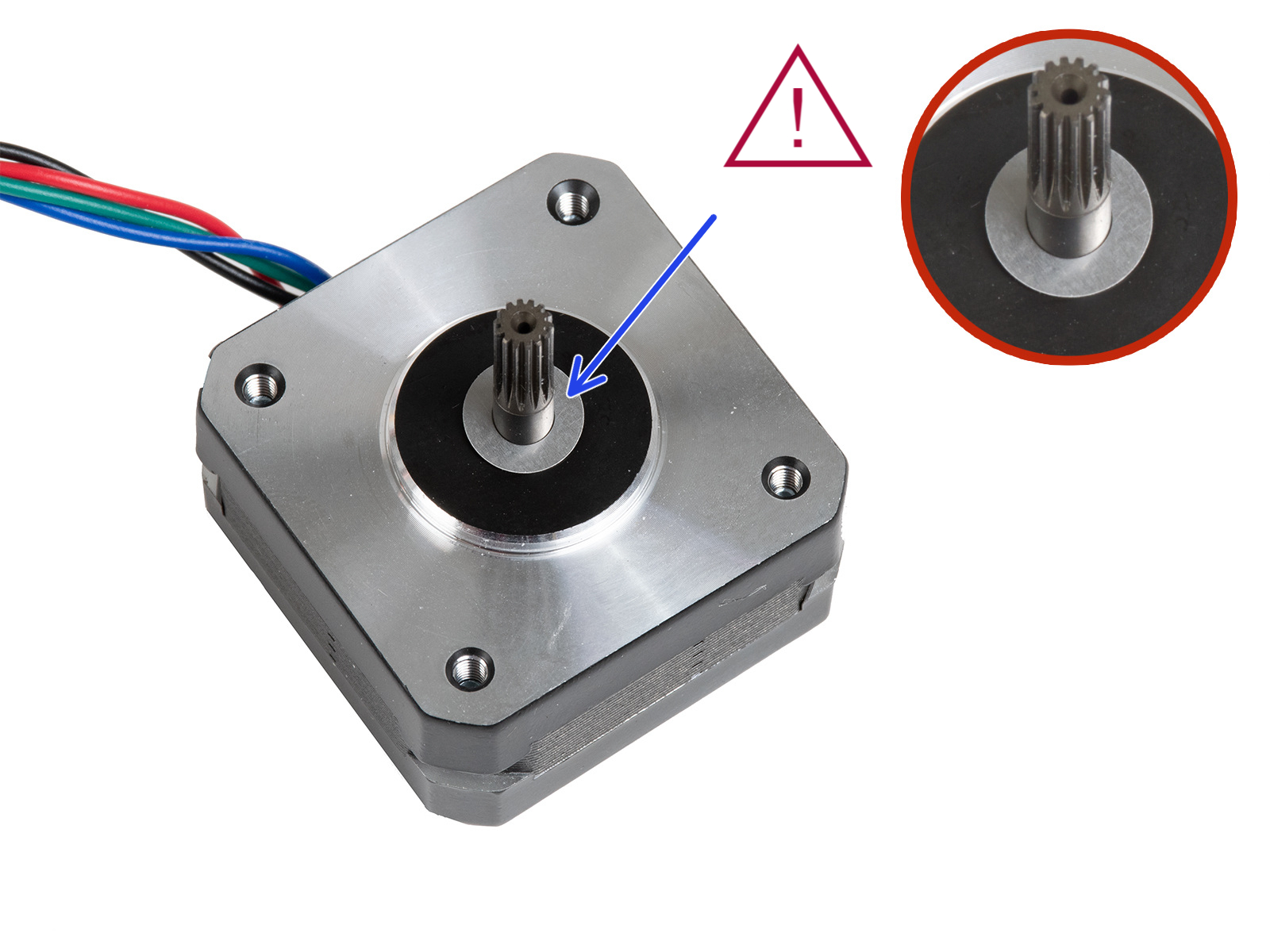
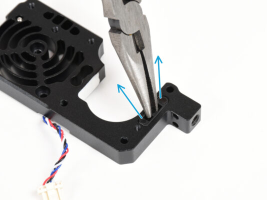
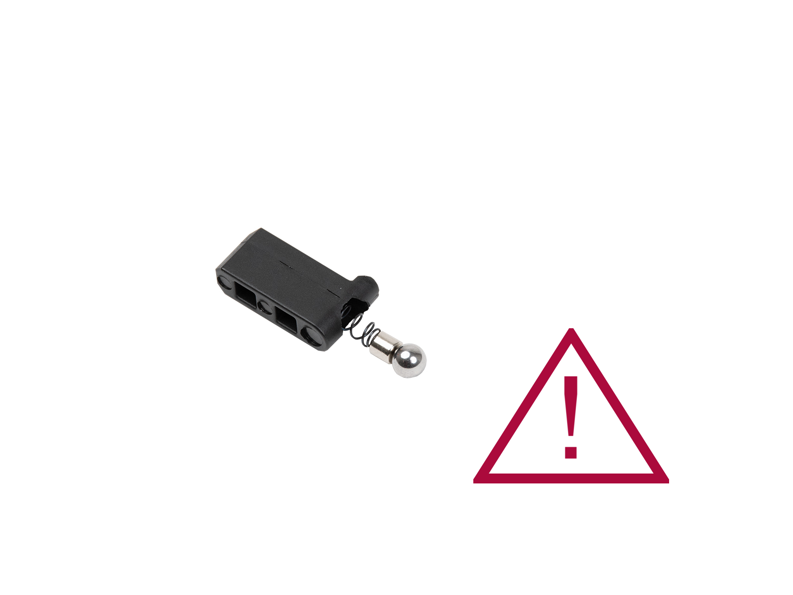
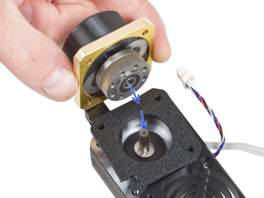
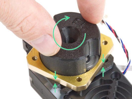
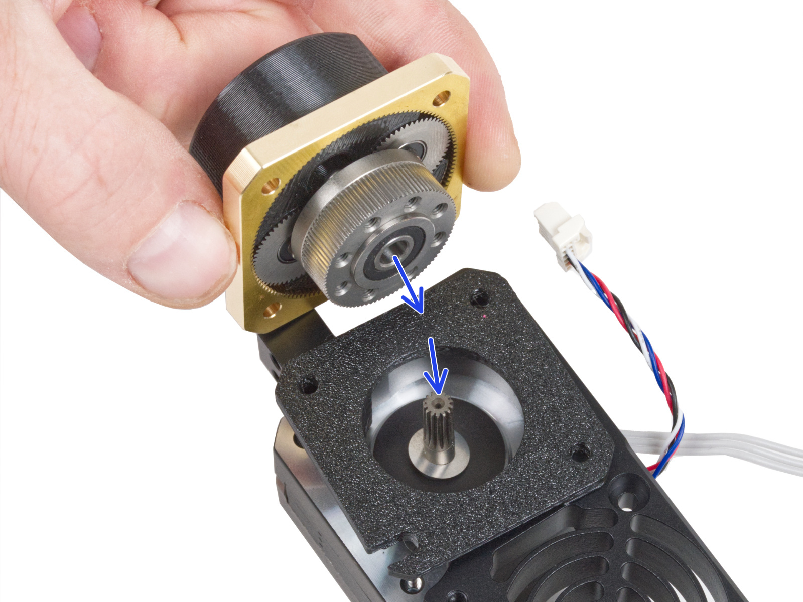
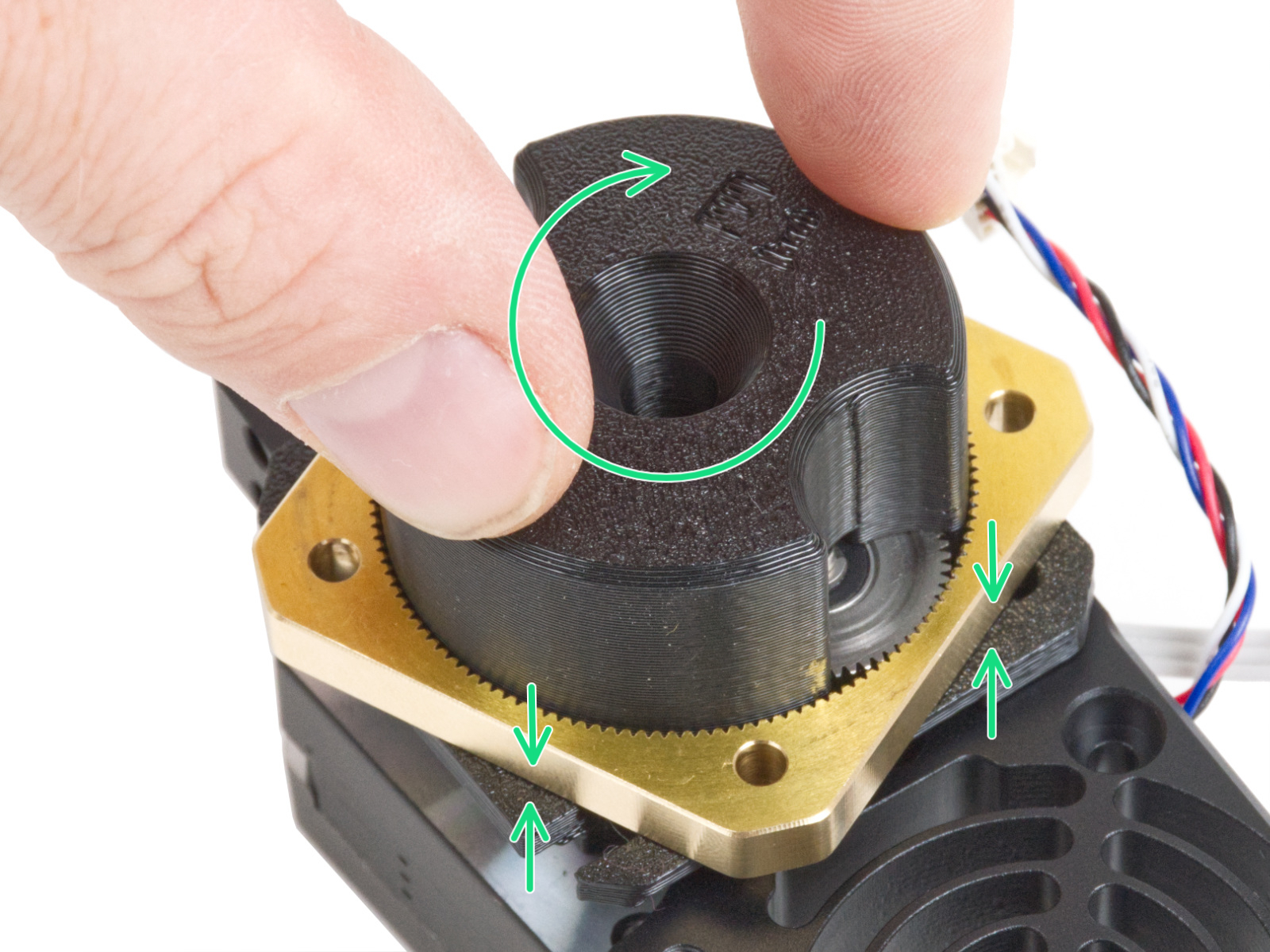
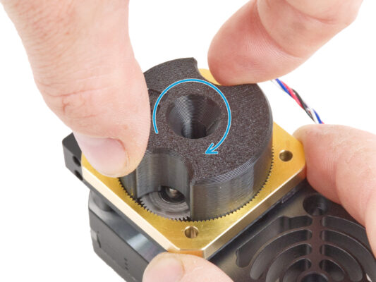
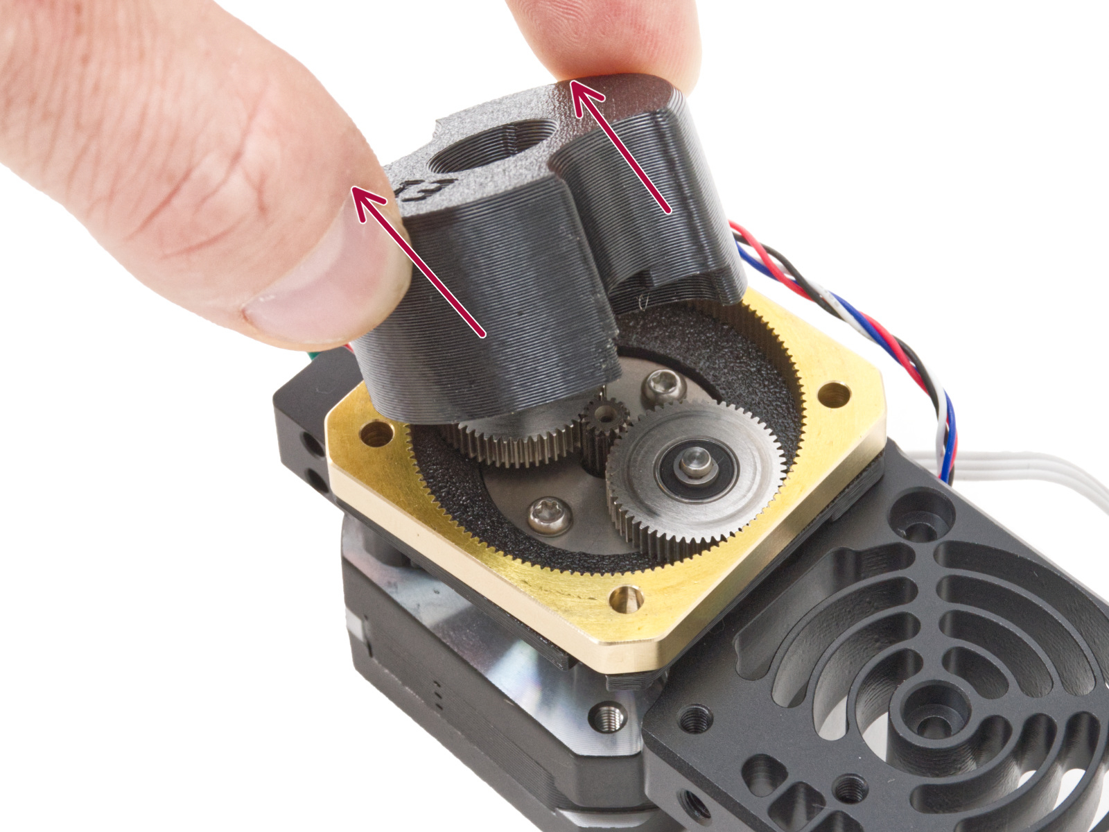
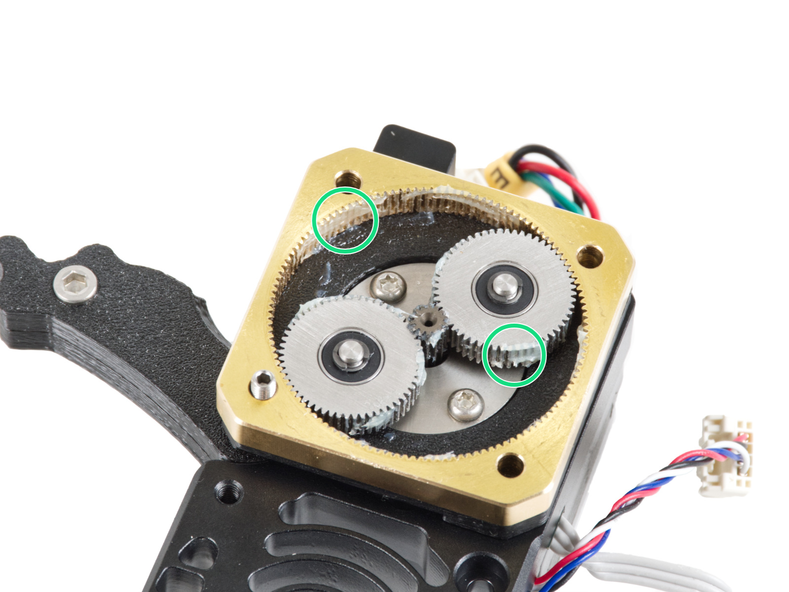
The following instructions require extreme attention. The procedure involves direct intervention in the planetary gearbox.
Preparation
Preparation
Preparation
Preparation
Before you start, make sure the extruder on your printer is in the middle of both the X and Z axes.
Unload filament from the printer and remove the spool holder.
Remove the steel sheet from the printer.
Power off your printer and disconnect it from the power.
Additional parts
Additional parts
Additional parts
For this guide, please prepare:
Prusa lubricant (1x) supplied with your printer
PG-assembly-adapter (1x)
The PG-assembly-adapter might not be included in the box and might need to be printed. You can download the STL file from https://www.printables.com/model/451501-mk4mk39-printable-parts.
The STL file is located in Nextruder section. Before proceeding, please ensure to review the recommended print settings provided in the caption.
DO NOT continue without the PG-assembly-adapter. It is necessary for the assembly!
The gearbox might be greasy. We recommend preparing a paper towel for wiping off the excess grease and dirt.
Protecting the heatbed
Before you proceed, it is recommended to protect the heatbed.
Take off the flexible steel sheet.
Use any cloth or piece of fabric, which is thick enough and cover the heatbed. This will ensure you won't damage (scratch) the surface during the disassembly.
Extruder removal (part 1)
Remove the loveboard cover on the extruder by lifting it up.
Remove the M3x10 screw from the right side and remove the side cover.
Remove the side cover.
Extruder removal (part 2)
There are safety latches on the front of each connector. The latch must be pushed inwards in order to be able to remove the connector. In case you can't reach the latch with your nails easily enough, use an appropriate tool to press the latch while you pull the connector out.
Disconnect the extruder motor connector.
Disconnect the Loadcell connector.
Disconnect the Filament sensor connector.
Open the fan-door.
Extruder removal (part 3)
From the other side of the extruder, disconnect the hotend heater connector. Note, the safety latch is in the front of the connector.
Disconnect the heatsink fan connector.
Disconnect both thermistor connectors. Note, the safety latch is on the left of each one.
Resease the two thumb screws holding the hotend assembly.
Release both the hotend heater and thermistor cables out of the groove inside the x-carriage.
Remove the hotend assembly by pulling it down.
Be extremely careful not to damage the cables!
Extruder removal (part 4)
Remove the two M3x18 screws holding the heatsink fan.
Remove the heatsink fan.
Remove the three M3x10 screws holding the heatsink.
Hold the extruder with your hand so that it doesn't fall off after you remove the heatsink screws!
Carefully remove the extruder assembly from the printer. Make sure not to damage any of the cables!
Extruder disassembly (part 1)
Remove the M3x4T grub screw using the short side of the T6 Torx key.
Remove the NTC heatsink thermistor. Be careful not to damage the cables.
Remove the two thumb screws on the side.
Extruder disassembly (part 2)
Remove both the M3x30 screws with the springs.
Remove the Idler-swivel assembly.
Remove the M3x25 screws.
There are several versions of the Nextruder. The earlier models feature four screws on the front, while the newer model is designed with three screws.
Remove the PG-case, the plastic cover on the front of the gearbox.
Extruder disassembly (part 3)
In case you have the "three screw" version of the Nextruder, remove the M3x25 set screw.
Remove the Idler assembly.
Remove the whole gearbox assembly: the printed main plate, the brass PG-ring and the gears.
Clean all the parts of the gearbox from excess grease and dirt.
Extruder disassembly (part 4)
Locate the metal washer that should be between the gearbox and the motor. It might be stuck to the gearbox assembly.
Earlier versions of the Nextruder use an orange spacer instead of the metal washer.
See the last picture for a reference.
Reseat the washer / spacer on the motor shaft, in case it has come off the shaft.
Remove the extruder motor from the heatsink.
Extruder disassembly (part 6)
BE EXTRA CAREFUL when removing the filament sensor. The filament sensor contains a tiny parts (spring, magnet, steel ball) that tend to fall out when the sensor is removed.
Very carefully pull the filament sensor out from the heatsink using the needle-nose pliers.
Don't lose the small parts! You will need them again later. Keep them aside in a safe place.
Installing the Hall sensor
Place the Hall filament sensor into the similarly shaped pocket in the heatsink.
Fix it with M2.5x6rT screw. Tighten it very carefully, you can crack the electronics board.
Installing the filament sensor
Insert the filament sensor assembly into the heatsink. Make sure the steel ball part is closer to the side of the heatsink.
Note the correct orientation of the assembly. There is a protrusion on the part. The protrusion must be facing down.
Push the assembly into the heatsink and make sure the filament sensor assembly is flush to the metal heatsink.
Assembling the extruder
Place the heatsink on the extruder motor. Note the orientation of both parts.
The motor cable must be facing "up".
The heatsink cables must be on the right side.
Attach the main-plate on the heatsink. Note the orientation of the part. Use the cutout as a guide.
Assembling the gearbox
The following instructions need to be done correctly and carefully. Achieve better understanding and successful assembly by watching the video alongside the guide: prusa.io/PG-assembly
After watching the video, follow the steps in this guide.
Attach the PG-assembly-adapter on the PG-assembly. Note the pockets for the gears in the adapter.
Assembling the PG-ring
Do not assemble the gearbox without the PG-assembly-adapter. This tool is intended to ensure that the gears are correctly fit together.
Slide the PG-ring onto the adapter.
Note there is a chamfer on one side of the PG-ring teeth. This side must be facing down (to the PG-assembly).
Grasp the entire assembly in one hand so that it can be rotated with the PG-ring.
With the other hand, slide the PG-ring onto the PG assembly in a wobbling motion (move the PG-ring left and right repeatedly) - a quarter turn is enough.
Stop when the surfaces of the gears are approximately flush with the surface of the PG ring.
Assembling the PG-assembly
Proceed very carefully in this step.
Maintain the position of the PG-assembly and attach it on to extruder motor shaft.
Very gently and freely rotate with the whole PG assembly (PG-assembly-adapter, PG-assembly and PG-ring) until it drops down so that there is no gap between the assembly and the main-plate. Do not push on the assembly.
Remove the PG-assembly-adapter.
Checking the PG-assembly
Attach the PG-assembly-adapter back on the PG-assembly again to verify that all parts are properly seated.
Rotate with the PG-assembly-adapter. The PG assembly must be easy to rotate without having to exert much force.
Remove the PG-adapter. You will no longer need it during assembly. We recommend keeping it for maintenance.
Ensure that the PG-assembly is not sticking out above the PG-ring. It should be positioned lower than the level of the PG-ring's surface or at the same level as the ring.
Ensure that the gap between the PG-ring and the Main-plate is minimal. If a significant gap is observed, disassemble the planetary gear assembly and reposition it.
Assembling the Nextruder idler
Insert the idler assembly between the PG-ring and the extruder motor. There is a cutout for the spacer in the main-plate. Line up the idler spacer with the hole in the PG-ring.
Secure both parts with the socket set screw 3x25. Do not overtighten the screw! The screw protrudes from the PG-ring after tightening. 
In case you have the 4-screw version of the Nextruder, you will install the M3x25 screw later on, instead of the set screw.
Apply a small amount of Prusa Lubricant all around the PG-ring and PG-assembly teeth.
Tip: apply a small amount of lubricant to the tip of the zip tie and then spread the lubricant over the gears.
Using a paper towel, wipe off any excess lubricant on the front surfaces.
Covering the planetary gear
Take the PG-case and make sure the Spacer 13x24x2,5 (plastic ring) is already inserted in the part.
The color of the plastic ring might vary. The properties are the same.
Cover the planetary gear and secure the PG-case with the M3x25 screws. Do not overtighten the screws!
Use three or four M3x25 screws, depending on the version of Nextruder you have.
Mounting the Idler-swivel assembly
Attach the spring 15x5 on both M3x30 screws.
Push the two screws with the springs through the holes in the protrusion on the heatsink. There are no threads inside.
Attach the Idler-swivel assembly on the screws. See the correct orientation of the Idler-nut. The side with version marking must be visible. See the picture.
Tighten both screws. Stop tightening as soon as the screw tips reach the front face of the idler nut.
Assembling the heatsink
On the extruder motor side, insert the NTC thermistor into the hole in the heatsink.
Secure it with the M3x4T grub screw. Screw it all the way in. Tighten gently, but firmly using two fingers and the short side of the T6 Torx key. Applying more force may cause permanent damage to the thread.
Insert two thumb screws into the heatsink. Do not tighten them completely. Two turns are enough for now.
Attaching the extruder
Place the Nextruder onto the spacers on the X-carriage.
Make sure the heatsink thermistor cable doesn't get pinched. It should be guided through the dedicated channel in the x-carriage.
Make sure none of the cables is getting pinched behind the extruder.
Align the heatsink holes with the spacers on the X-carriage and join both parts together with three M3x10 screws. Start with the middle one.
Ext. Cable management (part 1)
Connect the Loadcell cable into the Loveboard.
Connect the Filament sensor cable into the Loveboard.
Connect the E-motor cable into the Loveboard.
Connect the heatsink thermistor cable into the Loveboard.

Out of the two similar connectors, it goes to the connector on the right.
Carefully tuck the heatsink thermistor cable into the groove in the X-carriage.
Heatsink fan installation
Add the heatsink fan onto the extruder assembly. Make sure the cable is pointing to the left.
There is a sticker on the hotend fan, the sticker must be on the rear side of the fan - not visible.
Attach the fan using two M3x18 screws.
Connect the heatsink fan cable to the Loveboard.

Out of the two similar connectors, the heatsink fan connects to the lower one.
Tuck the fan cable into the groove on the X-carriage too.
Hotend assembly installation
Make sure the thumb screws on the side of the heatsink are loose.
Insert the hotend assembly into the heatsink from below.

Push it all the way up.
Make sure the hotend assembly is fully inserted.
Make sure the part of the hotend with the cables is pointing to the back of the printer, as seen in the picture.
After the hotend assembly is positioned correctly, hold it in place and tighten the two thumb screws fully.
Hotend cable management
Connect the hotend thermistor cable into the Loveboard.

Hotend / nozzle thermistor connects to the left of the two similar connectors.
Tuck the cable into the groove on the X-carriage.
Connect the hotend heater cable into the Loveboard.
Finally, tuck the cable into the groove on the X-carriage.
None of the cables should be sticking out of the groove. Otherwise, the print fan won't be able to close down into the operating position and might not work properly.
Once again, verify the thumb screws are tight.
LoveBoard: Wiring check
Before covering the electronics, check the connection of all cables. Click on high-resolution preview in the top left corner.
Close the idler mechanism before proceeding to the next step if you haven't already done so. Use the following sequence:
Close the extruder idler to the extruder
Close the idler-swivel and lock it over the extruder idler assembly
Covering the LoveBoard: side cover
Curve and arrange the cables on the right side of the extruder as you can see in the picture.
Cover the cables with the LoveBoard-cover-right.
Do not pinch the cables!
Secure it with the M3x10 screw.
Make sure the LoveBoard-cover-right fits snugly against the right side of the extruder. If not, it may cause the X-axis test to fail during the self-test because it will prevent the X-carriage assembly from moving all the way to the right.
Covering the LoveBoard: top cover
Push all cables to the extruder to make more space around them. See the picture.
Slide the Loveboard-cover on the extruder. And push it all the way down. The cover must go behind the X-carriage-back.
Be careful not to pinch any cables.
Ensure that the two plastic covers fit together perfectly.
Finishing up
Finishing up
Finishing up
Remove the protective cloth off the heatbed.
Attach the steel sheet back onto the printer.
Connect the printer to the electricity and turn it on.
Wizard - Selftest start

Visit the menu Control > Calibrations and tests and run all the calibrations starting with the first one.

The wizard will test all important components of the printer. The whole process takes a few minutes. Some parts of the wizard require direct user interaction. Follow the instruction on the screen.
NOTE: While testing the axes, make sure that there is nothing in the printer obstructing the axes movement.
WARNING: Do not touch the printer during the self-test unless prompted! Some parts of the printer may be HOT and moving at high speed.
The wizard starts with the fan check, Z-axis alignment and the X&Y axis test; all fully automatic.
Wizard - Loadcell Test
The next step of the wizard will prompt you to touch the nozzle to test and calibrate the Loadcell. During this procedure, the parts of the printer are not heated up so that you can touch them. Click Continue.
Do not touch the nozzle yet, wait until prompted by the Tap nozzle NOW message.
Tap the nozzle from below. In case the Loadcell does not detect the touch, you will be prompted to repeat the step. Otherwise, you will see Loadcell test passed OK when it succeeds.
Wizard - Gearbox Alignment
Once you get to the Gearbox Alignment part, select Continue and follow the on-screen instructions.
Undo the idler lock (swivel), then open the idler door.
Loosen the three screws on the front of the gearbox by 1.5 turns.
The printer will go through the automatic gearbox alignment. This process can’t be seen from the outside.
Once prompted, tighten the three screws in the pattern indicated on the screen.
Wizard - Filament Sensor Calibration
During the filament sensor calibration, you will need to use a short piece of filament. Prepare the filament and select Continue. There should be no filament inside the extruder before the start of the calibration process.
There should be no filament inside the extruder before the calibration process starts.
Once prompted to, insert the filament end into the opening on top of the extruder.
Remove the filament after the calibration finishes.
Was this guide helpful?

Comments

Still have questions?

Still have questions?

If you have a question about something that isn't covered here, check out our additional resources.
And if that doesn't do the trick, you can send an inquiry to [email protected] or through the button below.

Contact us